|
Disassembly, fixing of some small bits, examination of internals
February 2003
 |
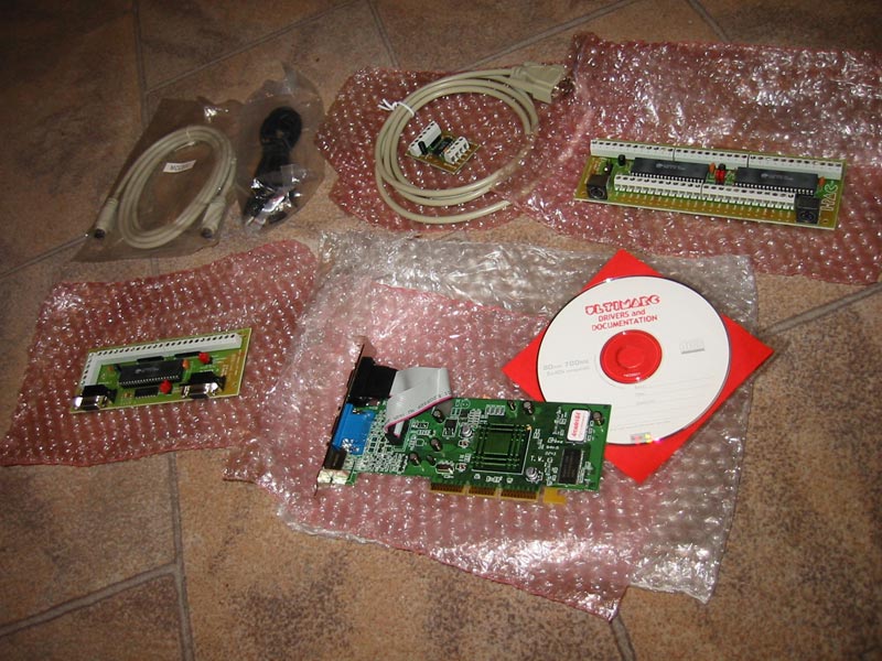
I received my shipment
from Ultimarc, as you can see. Clockwise from the top-left we have a
couple of cables (PS/2 link and USB-serial), the video amplifier and
arcade monitor cable, the I-PAC (which converts joystick and button
commands to keyboard presses so the computer can understand them), the
Opti-PAC (like the I-PAC but for optical devices like trackballs and
spinners), and finally the ArcadeVGA monitor card with driver CD. It needs
Windows 98/ME or XP to run so I think I'll go with 98. Also, in order to
run 2 trackballs I'll have to install MAME Analog+ and Win98 so that's
settled.
Now, the video amplifier is important in order to boost
the video signal from the graphics card to something of the level that a
normal arcade monitor can handle. There are some brands of monitor that
can take the low voltage out of a PC but if you don't know what yours is
like, buy the amplifier. I haven't heard of any monitor not handling this
boosted voltage level (but I won't buy you a new one if it blows up! Check
to make sure.)
An email from Bob Roberts on the 19th tells me he has my money and is
shipping my gear. ETA is 4-7 days. |
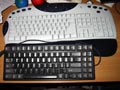 |
I spent some time
looking for a small keyboard to keep in my cabinet. I thought I might go
for wireless but there aren't too many choices, especially in a small
form-factor like this. However, after a few hours I remembered that I had
gutted on old portable PC in the mid-90s or so that had a removable
keyboard. A quick search in the shed and voila! Gave it a quick test and
it seems fine, except that the function key to access the numeric pad
sends out a TAB keypress (but otherwise works correctly.) Weird, but it
saves me some decent bucks. I've also ordered a PS/2 extension cable as
the one connected to the keyboard is pretty shrimpy. This little baby will
be hung from hooks inside the cabinet if I ever need it. I've got heaps of
wasted space inside the cabinet that I can't really use and this will fill
some of it nicely. |
 |
I've been looking at
car audio to use as a sound system. I was originally going to use a PC
setup with 2 speakers and a sub-woofer but had a change of mind. I'm
thinking now I'll use some car audio gear and give it a bit of kick. That
way I can also use the machine as an MP3 jukebox for parties or something.
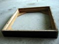
Here you can see the fruits of my labours in designing a box to enclose
the 10-inch sub-woofer in. You can't beat cardboard for decent mock-ups,
and things like this are invaluable to get a proper feel for what you
need. |
 |
Here you can see another shot of the mock-up showing the
angle of the rear face. It has to match that of the rear wall of the
cabinet and I've yet to really nail down what the angle is. I have no
specific tool to do it with, so armed with my high school trigonometry
skills and a tape measure I managed to devise a number of methods of
working it out. They gave me answers of either 74, 75 or 76 degrees so I'm
going with the average. Hopefully this will be close enough over the small
size involved. If it's out a bit I can probably use some foam to pad the
wall of the enclosure or something. We'll see. |
 |
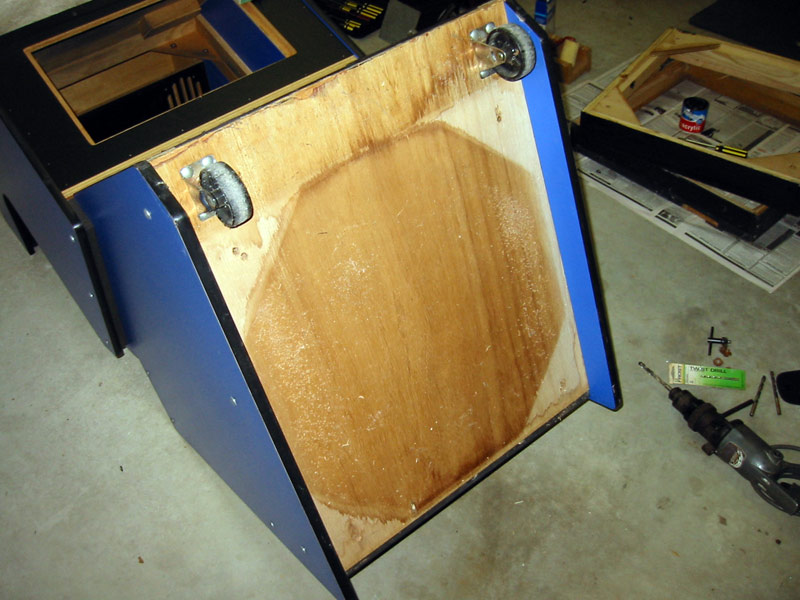
Here is the base of the
cabinet removed for a closer look. It is made out of plywood and has seen
a few kicks so I decided to build a replacement. There are heaps of screws
in it to try and firm it up a bit but it's just too nasty to keep. Now,
I'm pretty light-on for both woodworking skill and tools, so even
something as basic as this is going to be a bit of an adventure. The old
base is some really dodgy plywood. The new one will be a soft timber like
pine or something - it only has to take the weight along the short edge of
the timber so it shouldn't really matter. |
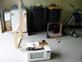 |
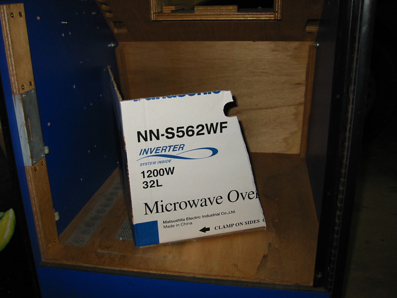
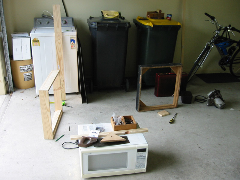
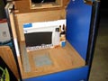
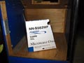
Here you can see what I
like to call the "poor man's workshop." My garage complete with wheelie-bins,
pushbike, and spare washing machine. In the foreground you can see my
saw-horse which saw previous life as a microwave oven (as featured HERE, if you feel like a laugh.)
The old base is on the right and my new one is partly constructed on the
left. I've decided to re-use the plywood triangle pieces to save me some
tricky sawing. Unfortunately I didn't plan things too well. Although I
knew my timber was thicker than the old stuff by about 3 or 4mm, I failed
to adjust the lengths of the sides to take this into account. This means
my frame is bigger, and the holes in the triangle pieces don't line up
with the bolt holes on the cabinet. What a twat! It's not like I'm unaware
of the old adage "measure twice, cut once", it's just that I
forgot all about it.
I put the frame on the cabinet and it still fits okay
(phew!) but I have to redrill some holes and remove the old t-nuts.
Hopefully the holes aren't too close together to make the fitting weak but
I won't be sure until I put the base on properly. |
 |
Here is the underside of the cabinet with the new holes
drilled. My base comes no further higher (towards the back) than the old
base, so it comes further forward. However, there is plenty of overhang on
the front so you won't really be able to tell. Plus the length difference
is only about 10mm at the most. While the cabinet is upside-down and I'm
painting the finished base frame (which is on the right sitting on top of
the old one) I decide to paint over some scratches in the back of the
cabinet. Works well and saves me from re-laminating the whole thing. I
also got some polyfiller out and filled in the holes left from taking the
padlock stuff off the cabinet. I'm going to paint over them with blue
paint sooner or later but that's pretty low on the list. I can't see any
reason to replace the whole side and front door just for a few little
holes. |
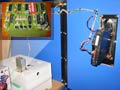 |
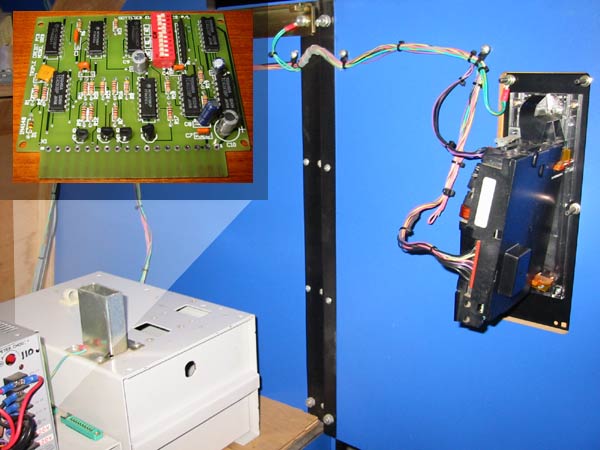
Now in the little
collage to the left you can see the coin mechanism and some other
hardware. The inset in the top left is the credit controller (or something
- I don't know what the proper technical term is.) I've put in a
translucent white shape that hopefully shows you where this PCB fits in
relation to everything else. It lies parallel with the power supply (the
thing with "110v" written on it) in a socket like the little
green one you can see beside it.
Anyway, the coin mech (a Mars ME111 if you're interested) I can work out -
it takes various voltages and spits out others depending on what coins are
put through. The controller, on the other hand, is a complete mystery. It
is supposed to tell the video game when a credit is supplied. So, you put
in $1 and it says "Hey! Put a credit up for this guy!" You put
in $2 and it sends 3 credits (or 2, depending on how stingy your arcade
is. Do they still give more credits when you put in larger denominations
or is this a thing from my childhood?) However, you need to put in quite a
few 20c pieces to get 1 credit (well, 5 anyway.)
It will be impossible to attach this to my PC
to handle credits correctly, according to MARK SCOTFORD - I'm a bit disappointed. The best I can do is get a credit
up whenever a coin I allow through the mech is put in. Good enough but not
perfect. Another option is to buy a credit controller from the UK for
about 40 Pounds (!) and write my own software. Not likely. Ah well, I
guess you have to lose some authenticity when you build a MAME cabinet. |
| |